Charlie Munger, Mental Models, and How to Build a $50T Company

Nosa Edoimioya

Founder & CEO
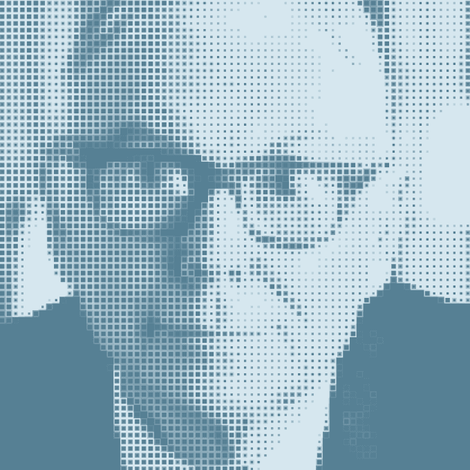
I recently read Poor Charlie’s Almanack by Peter D. Kaufman, which is a series of transcribed talks by the late Charles T. Munger (of Berkshire Hathaway). In these talks, Charlie lays out a peculiar process for structured thinking that he used throughout his life (in all his business and personal affairs). If you think about thinking for any amount of time, it becomes clear that most of us don’t have a structured way for general thinking. In specific domains, such as sales at a company ABC, we train employees to use certain processes when solving problems. However, when confronted with a new, complex, and interdisciplinary problem, it’s challenging to extrapolate because we don't have a latticework for general structured thinking.

Charlie sought out a structured process to think clearly. His solution was an interdisciplinary checklist that espoused all the major ideas from the major disciplines, many of which he learned on his own. The checklist includes ideas from mathematics (e.g., compound interest, Bayesian probability, inversion, etc.), science and engineering (e.g., critical mass, Darwinian evolution, backup systems, etc.), and psychology (e.g., social proof, sunk cost fallacy, etc.). When he encountered a new investment opportunity, he’d use a two-track analysis to evaluate it. First, he’d ask himself: “What are the factors that really govern the interests involved, rationally considered?” which considers the ideas that apply to the real interests, the real probabilities, and so forth. Second, he’d ask: “What are the subconscious influences where the brain is automatically making connections–which, by and large, are useful but often malfunction?” which evaluates the subconscious conclusions that people will come to due to psychological tendencies. Using his checklist, he thought about how each “big idea” might be affecting the real interests or subconscious conclusions.

This way of thinking served him well professionally and personally–to the tune of a $2.6B net worth at the time of his death. But most people don’t have a process like this. Worse, Charlie argues that most of the big ideas are really easy to grasp. Furthermore, most of them are taught in freshman (introductory) classes. Therefore, the main blocker to most people thinking in this way is that we haven’t made the effort to organize the ideas into a form that makes it easy to practice using them. Training oneself to learn all the major ideas in all the major disciplines and organize them in a latticework like Charlie’s seems like a worthwhile pursuit. We learn the best of what other people have already figured out (oftentimes through tremendous toil). Who wouldn’t want to have that? It’s like a shortcut through life and all that is required is reading, organization, and practice. What’s not to like?

The task of organizing my own latticework is one of the major intellectual pursuits of my life. This essay is my attempt to apply this thinking to Reforge Robotics. The rest of the essay follows a similar format to Talk Four in Poor Charlie’s Almanac, in which Charlie poses the hypothetical problem of starting and scaling a non-alcoholic beverage company with a $2 million investment in 1884 to be worth $2 trillion in 2034. This context allows Charlie to display his general thinking framework to answer the question of why the Coca-Cola company has been a tremendous success. I believe Charlie could have completed the same analysis to create the business plan for the Coca-Cola company in 1884 using his checklist without having the answer (i.e., the real Coca-Cola company) to analyze. In this essay, I attempt the same analysis for Reforge Robotics using the big ideas on my checklist. As with most lifelong pursuits, this analysis will be updated as I learn more. Okay, here’s the problem:

It is 2024 in Oakland. You are brought, along with 20 others like you, before a rich and eccentric Oakland citizen named Phitzer. Both you and Phitzer share two characteristics: first, you routinely use, in problem-solving, five helpful notions (shared below), and second, you know all the elementary ideas in all the basic college courses. Phitzer offers to invest $5 million, yet only take half the equity for a Phitzer Charitable Foundation, in a new corporation organized to go into the metal manufacturing business and remain in that business only, forever.

The other half of the equity will go to the person who most plausibly demonstrates that their business plan will cause Phitzer’s foundation to be worth $25 trillion 150 years later, in the money of that later time, 2174, despite paying out part of its earnings each year as a dividend. This will make the whole new corporation worth $50 trillion, even after paying out many trillions of dollars in dividends.

To get to a solution, we will use five helpful notions that Charlie uses in Talk Four.


  1. It is usually best to simplify problems by deciding the big no-brainer questions first.

  2. Use numerical fluency and mathematical principles to ascertain what the quantitative targets are.

  3. It is not enough to think problems through forward. You must also think in reverse.

  4. The best and most practical wisdom is elementary academic wisdom taken together in a multidisciplinary manner.

  5. Really big effects (lollapalooza effects) come from a large combination of factors.


Here is my solution, my pitch to Phitzer, using the five notions and what every bright college sophomore should know:

"Well, Phitzer, the big no-brainer decisions that, to simplify our problem, should be made first are as follows: First, we are never going to create something worth $50 trillion by making a new machine tool that is similar to existing machine tools and fighting for market share in a brutally competitive market, so we’ll have to focus on something completely different. Today, in the metal manufacturing business, there is a large focus on selling software licenses and services. However, software and services are also not enough because many companies sell software and services for existing machine tools and none of them have achieved the level of success we desire nor demonstrate the potential to reach that level of success in the future. Therefore, we have to combine new software with a different hardware design for manufacturing machines. When combined, the software and hardware need to work together to exceed customer expectations at a significantly lower cost. This will accomplish two results that we want: 1) our customers, contract manufacturers, who are also in a very competitive market, will feel that they are missing out on a competitive advantage if they do not buy our new and different hardware and software combination; and 2) since the combined software and hardware leads to a lower cost, our competition, the existing machine tool companies, will be slow to change because selling more expensive machines results higher revenues, higher sales commissions, higher system integration fees, etc. If we quickly make and distribute our products, we will establish a large lead with our software and hardware by the time they realize that they need to copy our products. At that point, it might be too late to turnover their businesses to compete with us. It will take a long time and consistent effort to accumulate this lead, but if we are successful, the knowledge we gain will give us an advantage for some time to come.

To considerably lower costs for our customers, it’s clear that we need to make both our own hardware and software. By making our own hardware, we retain three low-hanging fruit advantages: 1) we don’t need to pay the profit margin that other companies place on their products or the taxes for each transaction; 2) we become independent and don’t need to rely on the hardware provider to give us increasing access to their software to improve our product; and 3) we can design our hardware to have the technologies necessary to maximize the usefulness of our software. Making both hardware and software has been a no-brainer strategy for some of the most profitable companies. Others, who only make software, have strong monopolies from being early entrants into the software market and setting the software standards for the hardware manufacturers. We unfortunately do not have such favorable conditions in the century-old market of manufacturing.

One argument against this integrated hardware and software approach is that building new factories to make hardware requires a lot of upfront investment. To this, I pose two rebuttals: (a) it is short-sighted to focus on the millions we save today at the expense of the billions we will save tomorrow, and (b) as we significantly reduce the cost of manufacturing machines for our customers, we can use those same machines to reduce our cost. This creates a flywheel effect: our machines help to make copies of themselves, reducing the cost of our products, which further reduces the cost of our hardware.

It’s worth mentioning that, when we start the company, we will work on the software first and use commercial hardware instead of building our own hardware immediately. This choice will enable four things: 1) we can sell the packaged software and commercial hardware to early customers that fit into our target demographic to begin learning from the market; 2) we begin earning revenue quicker and limit the burden (both in time and equity) to raise more financing; 3) we can select the best qualities of the existing hardware(s) and combine them to design our own hardware, while solving for deficiencies; and 4) we solve most of the software challenges first and understand the areas where hardware provides a better solution than software. If we build the hardware first or both at the same time, it would be impossible to achieve the aforementioned qualities. In the software-only phase of the business, we will be capital efficient by working with robot integrators and financers, to provide the integration and financing services to our customers, while we serve solely as the software provider. Although we sacrifice profits from the high-margin integration and financing businesses, this trade-off will allow us to focus more resources on designing and manufacturing our hardware prototypes and iterating quickly to a useful solution, which will be more beneficial to us in the long term.

Accordingly, the characteristics of the hardware platform to accomplish our result are that it 1) is low-cost; and 2) can be combined with software to improve performance. Industrial robot arms have these characteristics and there are many case studies that have shown their efficacy in manufacturing when general purpose robot arms are combined with advanced software. They can both increase the efficiency of overall operations by automating repetitive processes and they can be used to conduct a subset of the metal manufacturing work. Scaling these case studies broadly will be achieved iteratively through research and development. Additionally, the robot arms we design specifically for manufacturing will further improve manufacturing performance.

Now that we’ve answered the no-brainer questions, we will next use numerical fluency to ascertain what our target of $50 trillion implies. It’s difficult to make estimations about the market 150 years from now. Nevertheless, there are two reasons why the 150-year target is useful: 1) we want to work towards conditions that allow the company to long outlive us, and 2) human demand for manufactured metal products is guaranteed to be conserved and very likely to grow significantly. Today, the United States has a median individual annual income of about $40,000 per year and its people enjoy many manufactured metal goods to obtain a relatively superior quality of life compared to the rest of the world. In contrast, the median annual global income is about $3,000 and, of the 8 billion people in the world, more than 7 billion live on lower incomes than the median US income. We can guess reasonably that by 2174, the fraction of people at the equivalent of a US median income in 2024 will be greater, which guarantees sustained demand for the current level of manufacturing machine tools, likely with periods of extreme demand as one region or another experiences significant growth. Today, approximately 500,000 CNC machines are sold annually at a growth rate of 4-6%. Assuming the growth is conserved, we can expect 1.5 billion units to be shipped in 2174. Thus, if our new machine, and other imitative machines in our new market, can supply over 25% of machine tools worldwide, and, with our fanaticism about low cost, we can occupy 40% of the new market, we can sell 150 million units in 2174. Assuming a profit of only $25,000 on each unit, we can reach $3.75 trillion of free cash flow on a revenue run rate of $37.5 trillion (assuming an average unit price of $250,000). This will be enough, given our business is still growing at a good rate, to make it easily worth $50 trillion.

A big question, of course, is whether $25,000 is a reasonable profit target for 2174. And the answer is yes if we can create a product with strong universal appeal. One hundred and fifty years is a long time and the dollar will almost surely suffer monetary depreciation. Concurrently, real purchasing power of the average consumer in the world will go way up. Her proclivity to purchase manufactured goods to improve her quality of life will go up considerably faster. Meanwhile, as technology improves, the cost of our product, in units of constant purchasing power, will go down. All four factors will work together in favor of our $25,000 per machine profit target. We also expect the cost of labor to rise with the purchasing power of the average consumer and the software that comes along with our machine will help replace a portion of labor from efficiency gains. The history of software teaches us that manufacturers will be willing to pay for the increased efficiency. Therefore, even if the hardware profit is only $10,000, the rest can be made up from the price of the software. Altogether, worldwide machine tool purchasing power in dollars will probably multiply by a factor of at least 5 over 150 years. Thinking in reverse, this makes our profit-per-machine target, under 2024 conditions, a mere one-fifth of $25,000, or $5,000. This is an easy to exceed target as we start out if our new product has universal appeal.

To create a product with universal appeal, we must tackle the two intertwined challenges of large scale. First, over 150 years, we must cause a new machine tool market to assimilate about one-fourth of the world’s machine tools. Second, we must operate so that 40% of the new market is ours while our competitors are left to share the remaining 60%. These results are lollapalooza results. Accordingly, we must attack our problem by causing every favorable factor we can think of to work for us. Plainly, only a powerful combination of many factors is likely to cause the lollapalooza consequences we desire.

Let’s start by exploring the consequences of our simplifying no-brainer decision that we need to combine software with a new hardware design for machine tools. This conclusion automatically leads to an understanding of our business in proper terms. We can see from the introductory course in psychology that, in essence, we are going into the business of creating and maintaining social proof by demonstrating the benefit of the new hardware and causing a large number of conversions to our machine tool system. It is not enough for our product to perform better than legacy products. Those products benefit from social proof and the change resistance inherent in man. The only solution to create behavior we seek is a new cult-like movement with a zealous missionary following. A movement with this characteristic is the only way to convince a large group of people to do something differently who have grown accustomed to doing things a certain way. We have to employ many characteristics of other successful movements (like religions):


  1. A mission that transcends the individuals/products, coupled with a missionary mandate which strongly encourages people in our movement to tell others about it.

  2. Strong admiration for people who use our products.

  3. Automatic word-of-mouth sharing, in social circles, about our movement. Telling a friend about our movement should be a no-brainer, universal benefit to both the teller and the hearer.

  4. Special classes of community members who have some status or benefit. For example, a special class for people who exclusively use our machines and get special benefits for this exclusivity. Classes will be prominently featured so that members aspire to reach status by, for example, exclusively using our machines.

  5. Physical communal aspects (e.g., a friendly feeling) by creating opportunities for our members to interact with each other and make new friends within the community, and bring their friends to meet others in the community.


To generate strong admiration for people who use our products, we will elevate their positive and moral character qualities, most of which have nothing to do with our product. We will profile qualities like their family life and their community contributions in an effort to get others to admire them greatly. We will also find already publicly admired figures and incentivize them to endorse our community. Additionally, if the qualities we focus on are associated with the larger mission of the community, the mission will be reinforced within the community. These activities will also support word-of-mouth sharing as admired persons will be talked about in circles where their values and the mission find resonance.

An important note is that the positive association must be created between admired persons and the movement/community, not our product or the company. Our product will simply benefit from an association with the movement, but it will need to demonstrate its merits to each customer independent of the movement.

Similarly, the community will have benefits (preferably free benefits) that are completely unrelated to the company or product, in addition to ones related to the company (e.g., discounts). On the company side, benefits will be integrated into a showroom as one of the physical spaces where community members interact with one another. Other benefits can include free meals, drinks, and gifts.

Since we’ve discussed forces that would favor the universal appeal of the company and product, we must now think in reverse to find forces that oppose it. What would make it more difficult to change the manufacturer’s mind? How can we ensure failure to introduce a new product and further entrench the incumbents? As usual, let’s start with the no-brainers:


  1. Our technology does not live up to existing machine tool performance or is worse.

  2. Our combined hardware and software system is more difficult to use than the existing manufacturing systems, creating puzzlement and stress.

  3. We attempt to force new manufacturers to make a fast decision about adopting our system and we don’t give them time to think through the decision and learn about how the system works. When forced to make a fast decision, the system with social proof will be chosen over ours.

  4. We focus on making comparisons to the existing systems instead of focusing on what our system can uniquely do, thereby pounding in the existing machines’ favorable qualities in user’s minds and creating avenues for debate.

  5. We display our product as having weak qualities and weak associations instead of displays of strength, which are associated with rigidity and precision.

  6. We highlight people who are using the existing machines and are successful and we ensure a mental association between their success and their existing machines.

  7. We first focus on getting older people, who tend to hate change, to change their behavior instead of focusing on younger people who are more likely to try something new.

  8. Over time, we maintain existing machine programming and workflow paradigms which makes it easy for customers to switch back to their older machines or for the old companies to create competing machines and use their reputation to recapture market share.


Avoiding factors 1-3 favors a slower rollout strategy where we validate the technology before rolling it out and give manufacturers the opportunity to gain familiarity with it. We will eliminate factors 4-6 with careful messaging to: (a) highlight only the unique features of our system and avoid making comparisons; (b) use strong names and strong qualities to describe our products; and (3) never advertise a positive story with machines that are not ours. Factor 7 is easy to eliminate by focusing on recruiting younger people first to join our movement and convincing them that our products are the future of manufacturing. Factor 8 is the most difficult to eliminate because we must lower the software adoption barrier (factor 2) for new users but quickly move existing customers to a new and improved programming and workflow paradigm. We will achieve this by maintaining multiple versions of software which change from the old to new paradigm one version at a time. The software will be compatible across versions and a process will be developed and updated to move users from the old complex software to the new simpler software over time. We may find that the new software is so simple and intuitive that our users are able to grasp it quickly, but the more likely outcome is that it will require training over time.

Well, that is my solution, Phitzer, to the problem of turning $5 million into $50 trillion even after paying out trillions of dollars in dividends. The correct strategies are clear after being related to elementary academic ideas brought into play by the helpful notions."

"The big money is not in the buying and selling, but in the waiting"

Charlie Munger

American Investor

Charlie sought out a structured process to think clearly. His solution was an interdisciplinary checklist that espoused all the major ideas from the major disciplines, many of which he learned on his own. The checklist includes ideas from mathematics (e.g., compound interest, Bayesian probability, inversion, etc.), science and engineering (e.g., critical mass, Darwinian evolution, backup systems, etc.), and psychology (e.g., social proof, sunk cost fallacy, etc.). When he encountered a new investment opportunity, he’d use a two-track analysis to evaluate it. First, he’d ask himself: “What are the factors that really govern the interests involved, rationally considered?” which considers the ideas that apply to the real interests, the real probabilities, and so forth. Second, he’d ask: “What are the subconscious influences where the brain is automatically making connections–which, by and large, are useful but often malfunction?” which evaluates the subconscious conclusions that people will come to due to psychological tendencies. Using his checklist, he thought about how each “big idea” might be affecting the real interests or subconscious conclusions.

Nosa Edoimioya

Founder & CEO

Share post
Written by

Nosa Edoimioya, Founder & CEO

Published on

Continue Reading

9/13/26

The Backlash Problem in Robotic Machining and What Software Can Do About It

By Nosa Edoimioya

Gear backlash is one of the largest sources of dimensional error in robotic milling. Here's what it does to your parts and how software-based compensation addresses it.

Robotic milling is gaining ground as an alternative to 5-axis CNC for large, complex, and low-volume parts. A KUKA KR 500, Fanuc M-900, or ABB IRB 6700 costs a fraction of a comparable gantry mill, offers a larger work envelope, and can be repurposed across part families. But accuracy remains the constraint that keeps many machining operations from making the switch.

One of the biggest contributors to that accuracy gap is backlash — and it shows up exactly where milling demands the most from the robot: at direction changes.

What is backlash?

Backlash is the small amount of free movement between mating mechanical components — particularly gears — when the direction of motion reverses. Every gear-driven joint in a robot arm has some backlash. It's a function of manufacturing tolerances, gear geometry, wear, and assembly.

The mechanism is straightforward. When a motor drives a joint in one direction, the gear teeth are in contact on one side. When the motor reverses, it must cross the backlash gap — the clearance between teeth — before the gear teeth engage on the opposite side and the joint begins moving again. During that crossing, the motor moves but the joint does not. The encoder reads a position change that hasn't happened at the link.

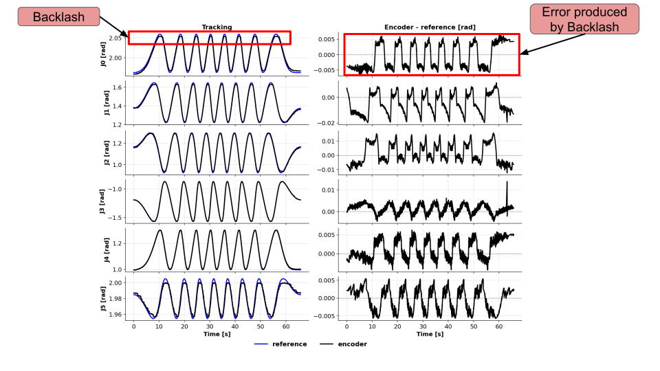
For a typical industrial robot, backlash per joint ranges from 0.05° to 0.3°. That sounds small, but it compounds. A 0.1° backlash error at a single joint propagates through the kinematic chain. At the end of a 2-meter arm, it becomes 3 mm or more of TCP positioning error.

Joint encoder readings and tracking error during repeated direction reversals

Encoder readings and tracking error during repeated reversals in the Reforge validation test.

Why milling exposes backlash more than other applications

Pick-and-place, welding, and palletizing applications often mask backlash because the robot moves in long, sweeping arcs with few reversals. The joints move predominantly in one direction for each segment of the path.

Milling is different. A robot following a contour — profiling a turbine blade root, machining an aircraft skin panel, or cutting a composite layup — reverses joint directions constantly. Every concave-to-convex transition, every pocket corner, every change in contour curvature forces one or more joints through a reversal. Each reversal triggers the backlash gap.

The result is visible on the part:

  • Witness marks at direction changes — small steps or ridges where the tool path shifts by the backlash error as joints reverse

  • Dimensional errors on contoured surfaces — the TCP tracks inside or outside the programmed path depending on the direction of approach

  • Surface finish degradation at corners and transitions — the tool dwells or skips as joints cross their backlash gaps, producing chatter marks or uneven material removal

  • Non-repeatable errors — because backlash depends on the direction of the last motion, the same programmed path can produce different results depending on how the robot arrived at each point

These errors are distinct from the robot's static accuracy specification. A robot with ±0.05 mm repeatability can still produce 1-3 mm of path error during contour milling if backlash is uncompensated.

How shops deal with backlash today

The current approaches all involve working around the problem rather than solving it:

Approach

What it does

Trade-off

Reduce feed rate

Slows the robot to minimize dynamic effects

Cycle time increases 2-5x; backlash gap still exists, just crossed more slowly

Harmonic drives

Reduces the physical clearance between gear teeth

Higher cost per joint; Add compliance on the robot which limits payload

CAM path compensation

Creates a tool path that avoids joint reversals instead of compensating for the backlash

Do not work for the for tool paths where backlash can not be avoided

Finishing passes with manual correction

Operator measures and corrects after the robot pass

Defeats the purpose of automation; adds labor cost per part

Buy a more expensive robot

Higher-end platforms with tighter mechanical tolerances

KUKA or Fanuc precision series costs 2-4x more; still has backlash, just less of it

None of these approaches address the root cause: the controller doesn't know the backlash exists and can't compensate for it in real time.

How software-based backlash compensation works

Software-based compensation operates between the trajectory planner and the robot's native servo controller. It tracks the direction of motion at each joint and applies a correction when a reversal is detected.

The process has two parts:

Calibration. The system drives each joint through a structured sequence of reversals and measures the actual deadband — the angular gap where the motor moves but the link does not. This is done once per robot and captures the specific backlash characteristics of that arm, including any asymmetry between joints and any configuration-dependent variation.

Real-time compensation. During operation, the software monitors the commanded trajectory for direction reversals at each joint. When a reversal is detected, it injects a correction equal to the identified deadband, so the motor crosses the backlash gap before the joint is expected to begin moving in the new direction. The joint starts its new motion already in contact — eliminating the lag.

This layer works alongside existing accuracy improvements. Kinematic calibration corrects the robot's geometric model. Dynamic joint tracking compensates for compliance and lag. Backlash compensation handles the direction-reversal error that neither of those can address. Together, they reduce the total path error to a level that starts approaching what many milling operations require.

Measured results

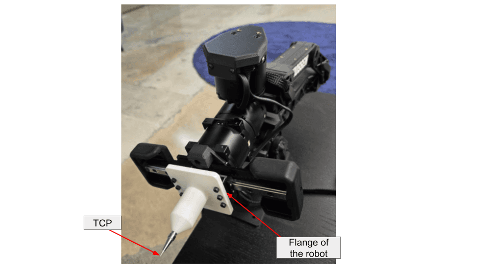
We validated backlash compensation on a trajectory specifically designed to force repeated joint reversals — the kind of multi-axis coordinated motion that robotic milling demands. The robot was commanded to track a circle with the flange center while holding the TCP fixed in Cartesian space, requiring all six joints to reverse direction continuously.

The validation setup: the metal tip marks the TCP, and the labeled flange follows the commanded circle.

Validation test setup with the metal-tip TCP and robot flange labeled

Metric

Without compensation

With compensation

Improvement

3-D TCP RMS tracking error

4.131 mm

0.878 mm

4.70×

All-joint RMS tracking error

0.593°

0.088°

6.75×

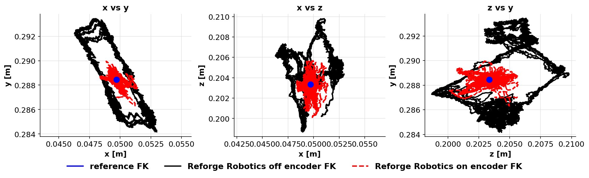
Estimated TCP position with Reforge software off and Joint Tracker plus Backlash Compensation on

Estimated TCP position in the validation test. Black is software off, red is Joint Tracker plus Backlash Compensation on, and blue marks the fixed reference. These measurements evaluate the combined software effect, not backlash compensation alone.

The per-joint results show that the compensation is effective across all joints, not just the ones with the largest backlash:

Joint

Without compensation

With compensation

Improvement

J0

0.330°

0.076°

4.37×

J1

0.948°

0.117°

8.11×

J2

0.927°

0.108°

8.59×

J3

0.320°

0.071°

4.52×

J4

0.319°

0.051°

6.26×

J5

0.204°

0.088°

2.32×

A 4.70× reduction in TCP tracking error during direction reversals changes what robotic milling can achieve. For a cell that was producing ±2 mm contour error, that drops to under ±0.5 mm — moving from rough machining territory into semi-finishing range without changing the robot, the spindle, or the CAM program.

What this means for your milling operation

Backlash compensation doesn't turn a robot arm into a 5-axis CNC. The robot still has structural compliance, thermal drift, and dynamic limitations that a purpose-built machine tool doesn't. But it removes one of the largest discrete error sources in robotic machining — and it does it through software, without mechanical modification.

For operations running KUKA, Fanuc, ABB, or other industrial platforms for milling, this means:

  • Tighter achievable tolerances on contoured surfaces and pocketed features — without slowing down

  • Reduced manual finishing after the robot pass — fewer witness marks, more consistent surface quality

  • Expanded part envelope — parts that previously required a CNC due to tolerance requirements may become viable on the robot cell

  • No hardware changes — deploys through the robot's existing command interface as a software layer

The economics are straightforward. If backlash is costing you a finishing pass, a manual correction step, or a reject rate on contoured parts, software compensation addresses the root cause at a fraction of the cost of upgrading the robot.

FAQ

Can software really fix a mechanical problem like backlash?
Software doesn't eliminate the physical gear clearance. It compensates for it by anticipating direction reversals and injecting corrective motion before the joint crosses the deadband. The gear teeth still have clearance — but the joint is already positioned to the correct side of the gap when the new motion begins.

Does backlash compensation work at high feed rates?
Yes. The compensation operates at the servo loop level, so it applies regardless of feed rate. In fact, higher speeds tend to benefit more because the dynamic effects of crossing the backlash gap — including the momentary loss of contact and the impact on re-engagement — are more pronounced at speed.

Which industrial robots have the worst backlash?
Backlash is present in every gear-driven robot. Robots with cycloidal or harmonic drive reducers (common in cobots and smaller industrial arms) tend to have less backlash than those with planetary gearboxes. However, even low-backlash drives accumulate wear over time. The actual backlash of a specific robot depends on its age, usage history, and maintenance. That's why per-robot calibration matters more than platform-level specifications.

How does this compare to buying a higher-precision robot?
A precision-grade industrial arm (e.g., KUKA KR Fortec Precision or Fanuc M-20iD/25 series) reduces backlash through tighter mechanical tolerances. The trade-off is cost — typically 2-4× the base model — and the backlash still increases with wear. Software compensation can be deployed on any arm and recalibrated as conditions change, at a fraction of the hardware upgrade cost.

Reforge Robotics builds control software that makes industrial robots more accurate. Backlash compensation is part of the Covalent Joint Tracker product. Book a demo to see it on your platform.

9/13/26

The Backlash Problem in Robotic Machining and What Software Can Do About It

By Nosa Edoimioya

Gear backlash is one of the largest sources of dimensional error in robotic milling. Here's what it does to your parts and how software-based compensation addresses it.

Robotic milling is gaining ground as an alternative to 5-axis CNC for large, complex, and low-volume parts. A KUKA KR 500, Fanuc M-900, or ABB IRB 6700 costs a fraction of a comparable gantry mill, offers a larger work envelope, and can be repurposed across part families. But accuracy remains the constraint that keeps many machining operations from making the switch.

One of the biggest contributors to that accuracy gap is backlash — and it shows up exactly where milling demands the most from the robot: at direction changes.

What is backlash?

Backlash is the small amount of free movement between mating mechanical components — particularly gears — when the direction of motion reverses. Every gear-driven joint in a robot arm has some backlash. It's a function of manufacturing tolerances, gear geometry, wear, and assembly.

The mechanism is straightforward. When a motor drives a joint in one direction, the gear teeth are in contact on one side. When the motor reverses, it must cross the backlash gap — the clearance between teeth — before the gear teeth engage on the opposite side and the joint begins moving again. During that crossing, the motor moves but the joint does not. The encoder reads a position change that hasn't happened at the link.

For a typical industrial robot, backlash per joint ranges from 0.05° to 0.3°. That sounds small, but it compounds. A 0.1° backlash error at a single joint propagates through the kinematic chain. At the end of a 2-meter arm, it becomes 3 mm or more of TCP positioning error.

Joint encoder readings and tracking error during repeated direction reversals

Encoder readings and tracking error during repeated reversals in the Reforge validation test.

Why milling exposes backlash more than other applications

Pick-and-place, welding, and palletizing applications often mask backlash because the robot moves in long, sweeping arcs with few reversals. The joints move predominantly in one direction for each segment of the path.

Milling is different. A robot following a contour — profiling a turbine blade root, machining an aircraft skin panel, or cutting a composite layup — reverses joint directions constantly. Every concave-to-convex transition, every pocket corner, every change in contour curvature forces one or more joints through a reversal. Each reversal triggers the backlash gap.

The result is visible on the part:

  • Witness marks at direction changes — small steps or ridges where the tool path shifts by the backlash error as joints reverse

  • Dimensional errors on contoured surfaces — the TCP tracks inside or outside the programmed path depending on the direction of approach

  • Surface finish degradation at corners and transitions — the tool dwells or skips as joints cross their backlash gaps, producing chatter marks or uneven material removal

  • Non-repeatable errors — because backlash depends on the direction of the last motion, the same programmed path can produce different results depending on how the robot arrived at each point

These errors are distinct from the robot's static accuracy specification. A robot with ±0.05 mm repeatability can still produce 1-3 mm of path error during contour milling if backlash is uncompensated.

How shops deal with backlash today

The current approaches all involve working around the problem rather than solving it:

Approach

What it does

Trade-off

Reduce feed rate

Slows the robot to minimize dynamic effects

Cycle time increases 2-5x; backlash gap still exists, just crossed more slowly

Harmonic drives

Reduces the physical clearance between gear teeth

Higher cost per joint; Add compliance on the robot which limits payload

CAM path compensation

Creates a tool path that avoids joint reversals instead of compensating for the backlash

Do not work for the for tool paths where backlash can not be avoided

Finishing passes with manual correction

Operator measures and corrects after the robot pass

Defeats the purpose of automation; adds labor cost per part

Buy a more expensive robot

Higher-end platforms with tighter mechanical tolerances

KUKA or Fanuc precision series costs 2-4x more; still has backlash, just less of it

None of these approaches address the root cause: the controller doesn't know the backlash exists and can't compensate for it in real time.

How software-based backlash compensation works

Software-based compensation operates between the trajectory planner and the robot's native servo controller. It tracks the direction of motion at each joint and applies a correction when a reversal is detected.

The process has two parts:

Calibration. The system drives each joint through a structured sequence of reversals and measures the actual deadband — the angular gap where the motor moves but the link does not. This is done once per robot and captures the specific backlash characteristics of that arm, including any asymmetry between joints and any configuration-dependent variation.

Real-time compensation. During operation, the software monitors the commanded trajectory for direction reversals at each joint. When a reversal is detected, it injects a correction equal to the identified deadband, so the motor crosses the backlash gap before the joint is expected to begin moving in the new direction. The joint starts its new motion already in contact — eliminating the lag.

This layer works alongside existing accuracy improvements. Kinematic calibration corrects the robot's geometric model. Dynamic joint tracking compensates for compliance and lag. Backlash compensation handles the direction-reversal error that neither of those can address. Together, they reduce the total path error to a level that starts approaching what many milling operations require.

Measured results

We validated backlash compensation on a trajectory specifically designed to force repeated joint reversals — the kind of multi-axis coordinated motion that robotic milling demands. The robot was commanded to track a circle with the flange center while holding the TCP fixed in Cartesian space, requiring all six joints to reverse direction continuously.

The validation setup: the metal tip marks the TCP, and the labeled flange follows the commanded circle.

Validation test setup with the metal-tip TCP and robot flange labeled

Metric

Without compensation

With compensation

Improvement

3-D TCP RMS tracking error

4.131 mm

0.878 mm

4.70×

All-joint RMS tracking error

0.593°

0.088°

6.75×

Estimated TCP position with Reforge software off and Joint Tracker plus Backlash Compensation on

Estimated TCP position in the validation test. Black is software off, red is Joint Tracker plus Backlash Compensation on, and blue marks the fixed reference. These measurements evaluate the combined software effect, not backlash compensation alone.

The per-joint results show that the compensation is effective across all joints, not just the ones with the largest backlash:

Joint

Without compensation

With compensation

Improvement

J0

0.330°

0.076°

4.37×

J1

0.948°

0.117°

8.11×

J2

0.927°

0.108°

8.59×

J3

0.320°

0.071°

4.52×

J4

0.319°

0.051°

6.26×

J5

0.204°

0.088°

2.32×

A 4.70× reduction in TCP tracking error during direction reversals changes what robotic milling can achieve. For a cell that was producing ±2 mm contour error, that drops to under ±0.5 mm — moving from rough machining territory into semi-finishing range without changing the robot, the spindle, or the CAM program.

What this means for your milling operation

Backlash compensation doesn't turn a robot arm into a 5-axis CNC. The robot still has structural compliance, thermal drift, and dynamic limitations that a purpose-built machine tool doesn't. But it removes one of the largest discrete error sources in robotic machining — and it does it through software, without mechanical modification.

For operations running KUKA, Fanuc, ABB, or other industrial platforms for milling, this means:

  • Tighter achievable tolerances on contoured surfaces and pocketed features — without slowing down

  • Reduced manual finishing after the robot pass — fewer witness marks, more consistent surface quality

  • Expanded part envelope — parts that previously required a CNC due to tolerance requirements may become viable on the robot cell

  • No hardware changes — deploys through the robot's existing command interface as a software layer

The economics are straightforward. If backlash is costing you a finishing pass, a manual correction step, or a reject rate on contoured parts, software compensation addresses the root cause at a fraction of the cost of upgrading the robot.

FAQ

Can software really fix a mechanical problem like backlash?
Software doesn't eliminate the physical gear clearance. It compensates for it by anticipating direction reversals and injecting corrective motion before the joint crosses the deadband. The gear teeth still have clearance — but the joint is already positioned to the correct side of the gap when the new motion begins.

Does backlash compensation work at high feed rates?
Yes. The compensation operates at the servo loop level, so it applies regardless of feed rate. In fact, higher speeds tend to benefit more because the dynamic effects of crossing the backlash gap — including the momentary loss of contact and the impact on re-engagement — are more pronounced at speed.

Which industrial robots have the worst backlash?
Backlash is present in every gear-driven robot. Robots with cycloidal or harmonic drive reducers (common in cobots and smaller industrial arms) tend to have less backlash than those with planetary gearboxes. However, even low-backlash drives accumulate wear over time. The actual backlash of a specific robot depends on its age, usage history, and maintenance. That's why per-robot calibration matters more than platform-level specifications.

How does this compare to buying a higher-precision robot?
A precision-grade industrial arm (e.g., KUKA KR Fortec Precision or Fanuc M-20iD/25 series) reduces backlash through tighter mechanical tolerances. The trade-off is cost — typically 2-4× the base model — and the backlash still increases with wear. Software compensation can be deployed on any arm and recalibrated as conditions change, at a fraction of the hardware upgrade cost.

Reforge Robotics builds control software that makes industrial robots more accurate. Backlash compensation is part of the Covalent Joint Tracker product. Book a demo to see it on your platform.

Industrial robot arm probing a compact kinematic calibration fixture

9/11/26

10 Minutes to 3-5x Better Accuracy: How Kinematic Calibration Works

By Iago Alves Pereira

What happens during a KineCal calibration — and why it takes minutes instead of days.

Kinematic calibration has historically been a specialist operation. A laser tracker, a trained metrology engineer, hours of setup, and a production line taken offline. The result is sub-millimeter accuracy that lasts until the robot drifts — and then you do it again.

We built KineCal to deliver comparable results in roughly 10 minutes, using the robot's own sensors and a calibration fixture that costs under $35. This post walks through what happens during those 10 minutes, how the system identification works, and what the measured results look like.

The problem KineCal solves

Every robot arm ships with a kinematic model — the mathematical description of its geometry that the controller uses to convert between joint angles and Cartesian positions. Link lengths, joint axis orientations, offsets, frame alignments.

The model is based on nominal design parameters. The physical machine is not nominal. Manufacturing tolerances, assembly variation, installation effects, and wear all create discrepancies between the model and the real geometry. The controller doesn't know the difference. It plans motions using an idealized machine, and the real machine deviates.

The result is positional error — typically 0.6 to 1.0mm on a standard 6-axis arm out of the box. That's the gap between where the controller thinks the TCP is and where it actually is.

KineCal identifies the real kinematic parameters from measured data and replaces the nominal model with one that matches the specific robot as installed.

What happens in 10 minutes

The calibration process has three steps. The first two run sequentially on the robot. The third runs in the cloud.

Step 1: Fixture setup (~2 minutes). The operator places a calibration fixture in the robot's workspace. The fixture is built from commodity hardware — an off-the-shelf bracket and reference features that can be assembled in under five minutes the first time, and under two minutes after that. No precision alignment is required. The system identifies the fixture's location from the measurement data, so approximate placement is sufficient.

The fixture provides known geometric constraints that the calibration algorithm uses to separate the robot's kinematic parameters from the fixture's position. In practice, this means the operator doesn't need to know the fixture's exact location — only that it's rigidly placed within reach.

Step 2: Automated measurement routine (~5 minutes). The operator runs a single command through the Reforge SDK. The robot executes a structured sequence of movements, approaching the calibration fixture from multiple configurations. At each configuration, the robot's joint encoders record the joint angles while the TCP contacts or approaches the fixture's reference features.

The measurement routine is designed to maximize observability of the kinematic parameters. It exercises the robot through configurations that expose each parameter's effect on TCP position — varying joint angles, approach directions, and arm configurations to decorrelate the parameters during identification.

The routine is fully automated. The operator starts it and waits. No manual teaching, no jogging, no point-by-point recording.

Step 3: Model identification (~3 minutes, cloud). The measurement data is uploaded to the Reforge API. The server runs a system identification algorithm that fits a kinematic model to the observed data.

The algorithm solves for the actual DH parameters — link lengths, joint offsets, twist angles, and link offsets — that best explain the measured joint configurations given the geometric constraints of the fixture. This is an optimization problem: find the kinematic parameters that minimize the residual error between the model's predicted TCP positions and the observed measurements.

The output is a calibrated kinematic model specific to that robot. It downloads and deploys as a software update through the SDK.

What the results look like

We've validated KineCal internally across multiple robot platforms. The consistent result is a 3x to 5x improvement in positional accuracy.

Before calibration: Typical TCP positional error of 0.6 to 1.0mm. This is the error from the nominal kinematic model — the gap between designed geometry and actual geometry.

After calibration: TCP positional error of 0.18 to 0.21mm. This is close to the repeatability limit of the robots we've tested — meaning the calibrated model has eliminated effectively all of the systematic kinematic error, and the remaining error is dominated by the robot's own mechanical precision.

The improvement ratio depends on how far the specific robot's geometry has drifted from nominal. A brand-new robot with tight manufacturing tolerances might start at 0.5mm and reach 0.18mm — roughly a 3x improvement. A robot with accumulated wear, a replaced joint, or a significant installation offset might start at 1.5mm and reach 0.20mm — closer to 7x.

The calibrated accuracy is consistent across the workspace. Unlike touch-up programming, which corrects individual waypoints, kinematic calibration corrects the underlying model. Every position the robot moves to benefits from the correction, not just the positions that were explicitly taught.

How calibration times compare across products

KineCal is one of three calibration products in the Reforge platform. The calibration time varies by product because each captures different properties of the robot:

  • Kinematic Calibration (KineCal): Static geometry — link lengths, joint offsets, frame alignments. Calibration time: ~10 minutes.

  • Joint Tracker: Per-joint dynamic response — lag, resonance, damping. Calibration time: ~5-10 minutes.

  • Vibration Compensation (Shaper): Full structural frequency response — how the robot amplifies and dampens motion across its frequency spectrum. Calibration time: up to 48 hours of data collection.

The vibration compensation number deserves context. The 48 hours of data collection can be spread across overnight runs over the course of a week. The robot collects calibration data during periods when it would otherwise be idle. It doesn't require dedicated downtime — the calibration runs alongside or in between production shifts.

The kinematic calibration and Joint Tracker calibrations are the fast ones. Both are designed to run during a scheduled maintenance window or as part of initial commissioning. Combined, they take under 20 minutes and deliver both the geometric correction (KineCal) and the dynamic feedforward compensation (Joint Tracker).

No laser tracker required

Traditional kinematic calibration depends on external metrology — typically a laser tracker system costing $50,000 to $150,000, plus a trained operator. The laser tracker provides ground-truth TCP measurements that the calibration algorithm uses to identify the kinematic parameters.

KineCal replaces the external measurement system with a structured fixture and the robot's own sensors. The geometric constraints of the fixture provide the equivalent of ground-truth reference — not by measuring the TCP's absolute position in space, but by providing known geometric relationships that the optimization algorithm uses to solve for the kinematic parameters.

The trade-off is straightforward. A laser tracker gives you absolute accuracy referenced to a calibrated metrology instrument. KineCal gives you accuracy referenced to the geometric constraints of a commodity fixture. For applications that require traceable metrology — aerospace machining, medical device manufacturing — the laser tracker is the right tool.

For everything else — and that's the majority of robotic applications — KineCal delivers comparable results at a fraction of the cost, time, and expertise. A $35 fixture, 10 minutes of robot time, and no metrology specialist.

When to calibrate

The question of when to calibrate comes up in every evaluation. The practical answer: calibrate at commissioning, and recalibrate on a schedule matched to your accuracy requirements.

For most applications, every six months is a reasonable starting cadence. Robots in heavy use, high-precision applications, or environments with significant thermal cycling benefit from more frequent calibration — monthly or even after every tool change.

The key enabler is that 10-minute calibration time. When calibration is fast enough to fit into a maintenance window, it stops being a special event and becomes a routine step. The economics of calibration change fundamentally when the process takes minutes instead of days.

Reforge Robotics builds open-source motion control software that makes robot calibration fast, affordable, and repeatable.

Industrial robot arm probing a compact kinematic calibration fixture

9/11/26

10 Minutes to 3-5x Better Accuracy: How Kinematic Calibration Works

By Iago Alves Pereira

What happens during a KineCal calibration — and why it takes minutes instead of days.

Kinematic calibration has historically been a specialist operation. A laser tracker, a trained metrology engineer, hours of setup, and a production line taken offline. The result is sub-millimeter accuracy that lasts until the robot drifts — and then you do it again.

We built KineCal to deliver comparable results in roughly 10 minutes, using the robot's own sensors and a calibration fixture that costs under $35. This post walks through what happens during those 10 minutes, how the system identification works, and what the measured results look like.

The problem KineCal solves

Every robot arm ships with a kinematic model — the mathematical description of its geometry that the controller uses to convert between joint angles and Cartesian positions. Link lengths, joint axis orientations, offsets, frame alignments.

The model is based on nominal design parameters. The physical machine is not nominal. Manufacturing tolerances, assembly variation, installation effects, and wear all create discrepancies between the model and the real geometry. The controller doesn't know the difference. It plans motions using an idealized machine, and the real machine deviates.

The result is positional error — typically 0.6 to 1.0mm on a standard 6-axis arm out of the box. That's the gap between where the controller thinks the TCP is and where it actually is.

KineCal identifies the real kinematic parameters from measured data and replaces the nominal model with one that matches the specific robot as installed.

What happens in 10 minutes

The calibration process has three steps. The first two run sequentially on the robot. The third runs in the cloud.

Step 1: Fixture setup (~2 minutes). The operator places a calibration fixture in the robot's workspace. The fixture is built from commodity hardware — an off-the-shelf bracket and reference features that can be assembled in under five minutes the first time, and under two minutes after that. No precision alignment is required. The system identifies the fixture's location from the measurement data, so approximate placement is sufficient.

The fixture provides known geometric constraints that the calibration algorithm uses to separate the robot's kinematic parameters from the fixture's position. In practice, this means the operator doesn't need to know the fixture's exact location — only that it's rigidly placed within reach.

Step 2: Automated measurement routine (~5 minutes). The operator runs a single command through the Reforge SDK. The robot executes a structured sequence of movements, approaching the calibration fixture from multiple configurations. At each configuration, the robot's joint encoders record the joint angles while the TCP contacts or approaches the fixture's reference features.

The measurement routine is designed to maximize observability of the kinematic parameters. It exercises the robot through configurations that expose each parameter's effect on TCP position — varying joint angles, approach directions, and arm configurations to decorrelate the parameters during identification.

The routine is fully automated. The operator starts it and waits. No manual teaching, no jogging, no point-by-point recording.

Step 3: Model identification (~3 minutes, cloud). The measurement data is uploaded to the Reforge API. The server runs a system identification algorithm that fits a kinematic model to the observed data.

The algorithm solves for the actual DH parameters — link lengths, joint offsets, twist angles, and link offsets — that best explain the measured joint configurations given the geometric constraints of the fixture. This is an optimization problem: find the kinematic parameters that minimize the residual error between the model's predicted TCP positions and the observed measurements.

The output is a calibrated kinematic model specific to that robot. It downloads and deploys as a software update through the SDK.

What the results look like

We've validated KineCal internally across multiple robot platforms. The consistent result is a 3x to 5x improvement in positional accuracy.

Before calibration: Typical TCP positional error of 0.6 to 1.0mm. This is the error from the nominal kinematic model — the gap between designed geometry and actual geometry.

After calibration: TCP positional error of 0.18 to 0.21mm. This is close to the repeatability limit of the robots we've tested — meaning the calibrated model has eliminated effectively all of the systematic kinematic error, and the remaining error is dominated by the robot's own mechanical precision.

The improvement ratio depends on how far the specific robot's geometry has drifted from nominal. A brand-new robot with tight manufacturing tolerances might start at 0.5mm and reach 0.18mm — roughly a 3x improvement. A robot with accumulated wear, a replaced joint, or a significant installation offset might start at 1.5mm and reach 0.20mm — closer to 7x.

The calibrated accuracy is consistent across the workspace. Unlike touch-up programming, which corrects individual waypoints, kinematic calibration corrects the underlying model. Every position the robot moves to benefits from the correction, not just the positions that were explicitly taught.

How calibration times compare across products

KineCal is one of three calibration products in the Reforge platform. The calibration time varies by product because each captures different properties of the robot:

  • Kinematic Calibration (KineCal): Static geometry — link lengths, joint offsets, frame alignments. Calibration time: ~10 minutes.

  • Joint Tracker: Per-joint dynamic response — lag, resonance, damping. Calibration time: ~5-10 minutes.

  • Vibration Compensation (Shaper): Full structural frequency response — how the robot amplifies and dampens motion across its frequency spectrum. Calibration time: up to 48 hours of data collection.

The vibration compensation number deserves context. The 48 hours of data collection can be spread across overnight runs over the course of a week. The robot collects calibration data during periods when it would otherwise be idle. It doesn't require dedicated downtime — the calibration runs alongside or in between production shifts.

The kinematic calibration and Joint Tracker calibrations are the fast ones. Both are designed to run during a scheduled maintenance window or as part of initial commissioning. Combined, they take under 20 minutes and deliver both the geometric correction (KineCal) and the dynamic feedforward compensation (Joint Tracker).

No laser tracker required

Traditional kinematic calibration depends on external metrology — typically a laser tracker system costing $50,000 to $150,000, plus a trained operator. The laser tracker provides ground-truth TCP measurements that the calibration algorithm uses to identify the kinematic parameters.

KineCal replaces the external measurement system with a structured fixture and the robot's own sensors. The geometric constraints of the fixture provide the equivalent of ground-truth reference — not by measuring the TCP's absolute position in space, but by providing known geometric relationships that the optimization algorithm uses to solve for the kinematic parameters.

The trade-off is straightforward. A laser tracker gives you absolute accuracy referenced to a calibrated metrology instrument. KineCal gives you accuracy referenced to the geometric constraints of a commodity fixture. For applications that require traceable metrology — aerospace machining, medical device manufacturing — the laser tracker is the right tool.

For everything else — and that's the majority of robotic applications — KineCal delivers comparable results at a fraction of the cost, time, and expertise. A $35 fixture, 10 minutes of robot time, and no metrology specialist.

When to calibrate

The question of when to calibrate comes up in every evaluation. The practical answer: calibrate at commissioning, and recalibrate on a schedule matched to your accuracy requirements.

For most applications, every six months is a reasonable starting cadence. Robots in heavy use, high-precision applications, or environments with significant thermal cycling benefit from more frequent calibration — monthly or even after every tool change.

The key enabler is that 10-minute calibration time. When calibration is fast enough to fit into a maintenance window, it stops being a special event and becomes a routine step. The economics of calibration change fundamentally when the process takes minutes instead of days.

Reforge Robotics builds open-source motion control software that makes robot calibration fast, affordable, and repeatable.

Robot in an automotive plant

9/4/26

Do You Need to Calibrate Every Robot?

By Iago Alves Pereira

When a model trained on one machine can cover the fleet — and when it can't.

One of the first questions we hear from teams evaluating Reforge is about scaling: if I calibrate one robot, do I need to calibrate every other robot of the same model?

The short answer is no — with a caveat that matters. A model trained on one unit of a given SKU will transfer to other units of the same SKU and deliver roughly 90% of the calibrated performance. The remaining 10% is the gap between nominally identical and physically identical. Whether that gap matters depends on your application.

This post explains what transfers across robots, what doesn't, and how to decide the right calibration strategy for your fleet.

What the model actually captures

When we calibrate a robot, we're building a mathematical model of how that specific machine behaves. For kinematic calibration, the model captures the real geometry — actual link lengths, joint axis orientations, offsets, and frame alignments as measured on the physical hardware. For dynamic calibration (vibration compensation and feedforward control), the model captures frequency response characteristics — how the robot amplifies or dampens motion at different frequencies, with what lag, and with what coupling between joints.

These properties come from two sources: the design of the robot and the specific physical instance.

Design-level properties are shared across all units of a SKU. The nominal link lengths, the gear ratios, the actuator types, the structural topology — these are determined by the engineering drawings and are consistent across the production run. A model captures these faithfully, and they transfer perfectly.

Instance-level properties vary from unit to unit. Manufacturing tolerances in link dimensions, joint axis alignment, gearbox backlash, bearing preload, cable routing, and assembly torques. These are small variations — typically tenths of a millimeter in geometry and single-digit percentage differences in dynamic parameters — but they compound through the kinematic chain and produce measurably different behavior at the TCP.

The 90% transfer

When you apply a model trained on Robot A to Robot B of the same SKU, you get the design-level correction for free. The systematic errors that all units of that model share — the difference between the nominal kinematic parameters and the actual average for that production run — are captured and corrected.

That correction alone is significant. On the platforms we've validated, the design-level error accounts for the majority of the total kinematic error. Correcting it brings most units from roughly 0.6-1.0mm of positional error down to the 0.2-0.3mm range.

The remaining instance-level error — the per-unit variation from manufacturing tolerances — is what the transferred model doesn't capture. It's real, but it's small relative to the uncalibrated baseline. This is what we mean by 90% of the performance: the transferred model eliminates most of the error, but the last increment of accuracy requires per-unit calibration.

When 90% is enough

For many applications, a transferred model is the right answer.

If your tolerance budget is 1mm and the uncalibrated robot has 2-3mm of error, a transferred model that brings every unit down to 0.2-0.3mm gives you substantial margin. You don't need per-unit calibration. You need one calibration per SKU, and every robot benefits.

This is the scaling story that matters for fleet operators. Calibrate one unit. Deploy the model across all units of that SKU. The marginal cost of adding the next robot is zero calibration time.

Applications where this works well:

  • Pick-and-place with tolerances above 0.5mm. The transferred model puts every unit well inside the budget.

  • Palletizing and machine tending. These applications are tolerance-friendly and benefit primarily from the speed improvement that vibration compensation provides. The dynamic model transfers well across units because the structural design is shared.

  • Visual inspection at fixed stations. If the robot moves to inspection positions and stops, the accuracy requirement is at the waypoints only. A transferred kinematic model is usually sufficient.

When you need per-unit calibration

The 10% gap matters when your application consumes the full accuracy budget.

If your tolerance is 0.3mm and the transferred model delivers 0.2-0.3mm, you're operating at the margin. Some units will pass. Others won't. The variation between units becomes the limiting factor.

Per-unit calibration closes the gap. Calibrating the specific robot identifies its actual geometry — not the average geometry of its SKU — and produces a model that reaches the platform's accuracy floor. On our validated platforms, that floor is approximately 0.18-0.21mm.

Applications where per-unit calibration matters:

  • Precision assembly and insertion tasks. Connector insertion, pin alignment, and similar operations where the tolerance is smaller than the per-unit variation.

  • Offline programming without touch-up. If the goal is to generate paths in simulation and run them on the real robot without manual correction, per-unit accuracy is the requirement. The transferred model gets close. Per-unit calibration eliminates the remaining teaching step.

  • Multi-robot coordination. When two or more robots need to agree on the location of a shared workspace, their individual kinematic errors need to be independently corrected. A shared model doesn't resolve the relative error between units.

  • Quality-critical applications where out-of-tolerance means scrap — welding, dispensing, laser processing — and the cost of a single bad part exceeds the cost of calibrating the robot.

The practical approach

The calibration strategy that makes sense for most fleets is a two-tier approach.

Tier 1: One model per SKU. Calibrate one robot of each model in your fleet. Deploy that model across all units of the same SKU. This covers the design-level error and handles the majority of the accuracy improvement with minimal effort.

Tier 2: Per-unit calibration where needed. For robots in precision applications, or for units that show higher-than-expected error with the transferred model, run per-unit calibration. The process takes roughly 10 minutes for kinematic calibration. It can be integrated into commissioning workflows or run during scheduled maintenance.The process for other products is similar because our system fine-tunes the base model, combining the initial data with a smaller dataset.

The key advantage of this approach is that per-unit calibration is not expensive. With Reforge's KineCal, the calibration fixture costs under $35 in commodity hardware. The measurement routine is automated through the SDK. The model fitting runs in the cloud. An operator can calibrate a robot without metrology expertise or specialized equipment.

When calibration takes 10 minutes and costs effectively nothing in equipment, the question shifts from "can we afford to calibrate every robot?" to "is there a reason not to?"

Recalibration and drift

The transferability question also has a time dimension. A model trained today captures the robot's current state. Over months, mechanical wear changes the properties — gearbox backlash increases, bearings develop play, structural characteristics shift.

We recommend recalibrating at a minimum every six months. Robots in heavy-use or high-precision applications benefit from more frequent calibration — even as often as monthly. The calibration process is designed to run during scheduled downtime or overnight without taking the robot offline during production.

A continuous monitoring feature is on our roadmap that would use ongoing data collection to detect drift and trigger recalibration automatically. Until then, scheduled recalibration at a cadence matched to your application's tolerance budget is the practical approach.

The bottom line

You don't need to calibrate every robot from day one. A model trained on one unit covers the fleet at roughly 90% of the calibrated performance. For most applications, that's more than sufficient.

Where the last 10% matters — precision assembly, offline programming, multi-robot coordination — per-unit calibration/fine-tuning closes the gap in about 10 minutes with no specialized equipment.

The practical strategy: calibrate one per SKU as the baseline, then per-unit where the application demands it. Scale the fleet first. Calibrate precisely where it counts.

Reforge Robotics builds advanced motion control software that makes robot calibration fast, affordable, and repeatable.

Robot in an automotive plant

9/4/26

Do You Need to Calibrate Every Robot?

By Iago Alves Pereira

When a model trained on one machine can cover the fleet — and when it can't.

One of the first questions we hear from teams evaluating Reforge is about scaling: if I calibrate one robot, do I need to calibrate every other robot of the same model?

The short answer is no — with a caveat that matters. A model trained on one unit of a given SKU will transfer to other units of the same SKU and deliver roughly 90% of the calibrated performance. The remaining 10% is the gap between nominally identical and physically identical. Whether that gap matters depends on your application.

This post explains what transfers across robots, what doesn't, and how to decide the right calibration strategy for your fleet.

What the model actually captures

When we calibrate a robot, we're building a mathematical model of how that specific machine behaves. For kinematic calibration, the model captures the real geometry — actual link lengths, joint axis orientations, offsets, and frame alignments as measured on the physical hardware. For dynamic calibration (vibration compensation and feedforward control), the model captures frequency response characteristics — how the robot amplifies or dampens motion at different frequencies, with what lag, and with what coupling between joints.

These properties come from two sources: the design of the robot and the specific physical instance.

Design-level properties are shared across all units of a SKU. The nominal link lengths, the gear ratios, the actuator types, the structural topology — these are determined by the engineering drawings and are consistent across the production run. A model captures these faithfully, and they transfer perfectly.

Instance-level properties vary from unit to unit. Manufacturing tolerances in link dimensions, joint axis alignment, gearbox backlash, bearing preload, cable routing, and assembly torques. These are small variations — typically tenths of a millimeter in geometry and single-digit percentage differences in dynamic parameters — but they compound through the kinematic chain and produce measurably different behavior at the TCP.

The 90% transfer

When you apply a model trained on Robot A to Robot B of the same SKU, you get the design-level correction for free. The systematic errors that all units of that model share — the difference between the nominal kinematic parameters and the actual average for that production run — are captured and corrected.

That correction alone is significant. On the platforms we've validated, the design-level error accounts for the majority of the total kinematic error. Correcting it brings most units from roughly 0.6-1.0mm of positional error down to the 0.2-0.3mm range.

The remaining instance-level error — the per-unit variation from manufacturing tolerances — is what the transferred model doesn't capture. It's real, but it's small relative to the uncalibrated baseline. This is what we mean by 90% of the performance: the transferred model eliminates most of the error, but the last increment of accuracy requires per-unit calibration.

When 90% is enough

For many applications, a transferred model is the right answer.

If your tolerance budget is 1mm and the uncalibrated robot has 2-3mm of error, a transferred model that brings every unit down to 0.2-0.3mm gives you substantial margin. You don't need per-unit calibration. You need one calibration per SKU, and every robot benefits.

This is the scaling story that matters for fleet operators. Calibrate one unit. Deploy the model across all units of that SKU. The marginal cost of adding the next robot is zero calibration time.

Applications where this works well:

  • Pick-and-place with tolerances above 0.5mm. The transferred model puts every unit well inside the budget.

  • Palletizing and machine tending. These applications are tolerance-friendly and benefit primarily from the speed improvement that vibration compensation provides. The dynamic model transfers well across units because the structural design is shared.

  • Visual inspection at fixed stations. If the robot moves to inspection positions and stops, the accuracy requirement is at the waypoints only. A transferred kinematic model is usually sufficient.

When you need per-unit calibration

The 10% gap matters when your application consumes the full accuracy budget.

If your tolerance is 0.3mm and the transferred model delivers 0.2-0.3mm, you're operating at the margin. Some units will pass. Others won't. The variation between units becomes the limiting factor.

Per-unit calibration closes the gap. Calibrating the specific robot identifies its actual geometry — not the average geometry of its SKU — and produces a model that reaches the platform's accuracy floor. On our validated platforms, that floor is approximately 0.18-0.21mm.

Applications where per-unit calibration matters:

  • Precision assembly and insertion tasks. Connector insertion, pin alignment, and similar operations where the tolerance is smaller than the per-unit variation.

  • Offline programming without touch-up. If the goal is to generate paths in simulation and run them on the real robot without manual correction, per-unit accuracy is the requirement. The transferred model gets close. Per-unit calibration eliminates the remaining teaching step.

  • Multi-robot coordination. When two or more robots need to agree on the location of a shared workspace, their individual kinematic errors need to be independently corrected. A shared model doesn't resolve the relative error between units.

  • Quality-critical applications where out-of-tolerance means scrap — welding, dispensing, laser processing — and the cost of a single bad part exceeds the cost of calibrating the robot.

The practical approach

The calibration strategy that makes sense for most fleets is a two-tier approach.

Tier 1: One model per SKU. Calibrate one robot of each model in your fleet. Deploy that model across all units of the same SKU. This covers the design-level error and handles the majority of the accuracy improvement with minimal effort.

Tier 2: Per-unit calibration where needed. For robots in precision applications, or for units that show higher-than-expected error with the transferred model, run per-unit calibration. The process takes roughly 10 minutes for kinematic calibration. It can be integrated into commissioning workflows or run during scheduled maintenance.The process for other products is similar because our system fine-tunes the base model, combining the initial data with a smaller dataset.

The key advantage of this approach is that per-unit calibration is not expensive. With Reforge's KineCal, the calibration fixture costs under $35 in commodity hardware. The measurement routine is automated through the SDK. The model fitting runs in the cloud. An operator can calibrate a robot without metrology expertise or specialized equipment.

When calibration takes 10 minutes and costs effectively nothing in equipment, the question shifts from "can we afford to calibrate every robot?" to "is there a reason not to?"

Recalibration and drift

The transferability question also has a time dimension. A model trained today captures the robot's current state. Over months, mechanical wear changes the properties — gearbox backlash increases, bearings develop play, structural characteristics shift.

We recommend recalibrating at a minimum every six months. Robots in heavy-use or high-precision applications benefit from more frequent calibration — even as often as monthly. The calibration process is designed to run during scheduled downtime or overnight without taking the robot offline during production.

A continuous monitoring feature is on our roadmap that would use ongoing data collection to detect drift and trigger recalibration automatically. Until then, scheduled recalibration at a cadence matched to your application's tolerance budget is the practical approach.

The bottom line

You don't need to calibrate every robot from day one. A model trained on one unit covers the fleet at roughly 90% of the calibrated performance. For most applications, that's more than sufficient.

Where the last 10% matters — precision assembly, offline programming, multi-robot coordination — per-unit calibration/fine-tuning closes the gap in about 10 minutes with no specialized equipment.

The practical strategy: calibrate one per SKU as the baseline, then per-unit where the application demands it. Scale the fleet first. Calibrate precisely where it counts.

Reforge Robotics builds advanced motion control software that makes robot calibration fast, affordable, and repeatable.

See what Reforge can improve on your robot

Bring one representative trajectory or error dataset. We’ll identify the relevant product, required inputs, and a bounded evaluation plan.

See what Reforge can improve on your robot

Bring one representative trajectory or error dataset. We’ll identify the relevant product, required inputs, and a bounded evaluation plan.

Reforge Robotics

100 Speedway Drive, Suite 445B

San Leandro, California 94609