What 5x Accuracy Actually Means for Teleoperation

Iago Alves Pereira
Co-Founder and CTO

How we validated Joint Tracker's tracking improvement and what the data tells us about teleoperation performance.
We validated Joint Tracker on two 6-axis robot platforms. The goal was to measure how much model-based feedforward control actually reduces tracking error, and to understand what that reduction means for teleoperation — where tracking fidelity directly determines what tasks the system can perform.
This post walks through the validation methodology, the measured results, what drives the improvement, and why it matters for teams building teleoperation systems.
How we measured it
The validation methodology is straightforward.
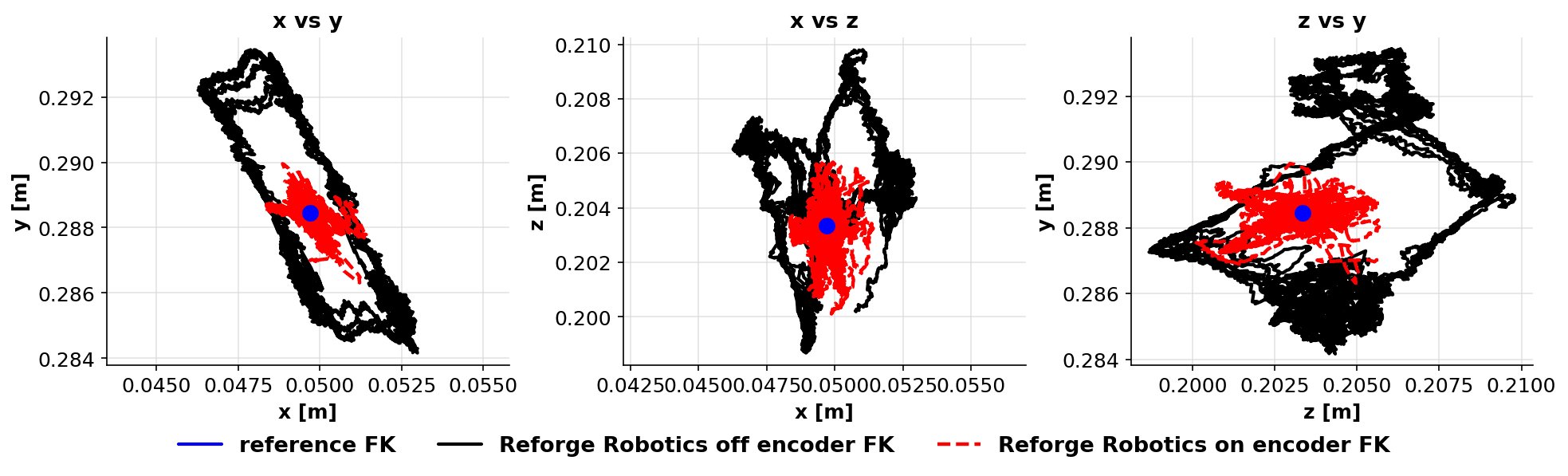
We define a trajectory in task space and use inverse kinematics to convert it to joint space. The robot executes the trajectory while we capture encoder readings at each joint. We then apply forward kinematics to the encoder data to compute the actual TCP position throughout the motion.
We run this twice: once with Joint Tracker off (the robot's stock controller executing the trajectory directly) and once with Joint Tracker on. Both runs are compared against the desired trajectory.
The metric is RMS tracking error — computed per-joint in degrees and per-axis at the TCP in millimeters. Joint-level error tells you how well each actuator follows the reference. TCP error tells you what the end-effector actually does — which is what the operator experiences.
On the first platform, we swept speed from 1.0x to 2.5x nominal to see how tracking degrades with speed. On the second, we validated at 5.0x speed scale — well beyond the trajectory's original timing.
Results
Platform A (6-axis arm used in teleoperation applications):
TCP tracking error: 7.6mm → 1.9mm (4.1x improvement)
Joint tracking error: 1.12° → 0.24° (4.6x improvement, averaged across joints)
Per-joint improvements ranged from 1.9x to 9.2x
Per-axis TCP improvements: 6.0x (X), 6.1x (Y), 2.0x (Z)
Measured at top speed scale of 2.5x
The Z-axis improvement is notably lower than X and Y. This tells us the dynamics along Z are harder to compensate — likely because the Z-axis loads gravity more directly, and the structural compliance in that direction is different. The joint-level data is consistent with this: the joints most loaded by gravity showed smaller improvement ratios.
Platform B (6-axis arm):
TCP tracking error: 10.9mm → 1.9mm (5.7x improvement)
Joint tracking error: 1.51° → 0.18° (8.6x improvement, averaged across joints)
Per-joint improvements ranged from 4.7x to 15.7x
Per-axis TCP improvements: 8.6x (X), 4.9x (Y), 4.0x (Z)
Measured at 5.0x speed scale
The larger improvement on Platform B is partly because the baseline error was worse — 10.9mm versus 7.6mm at the TCP. The converged accuracy with Joint Tracker on is nearly identical on both platforms (1.9mm), which tells us the controller is bringing both robots to roughly the same performance floor regardless of how poor the stock tracking was.
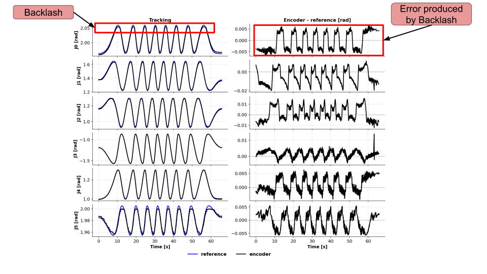
This result is important. It suggests the residual 1.9mm error is dominated by effects the current model doesn't capture — backlash, higher-frequency structural modes, or sensor resolution — rather than by the controller itself.
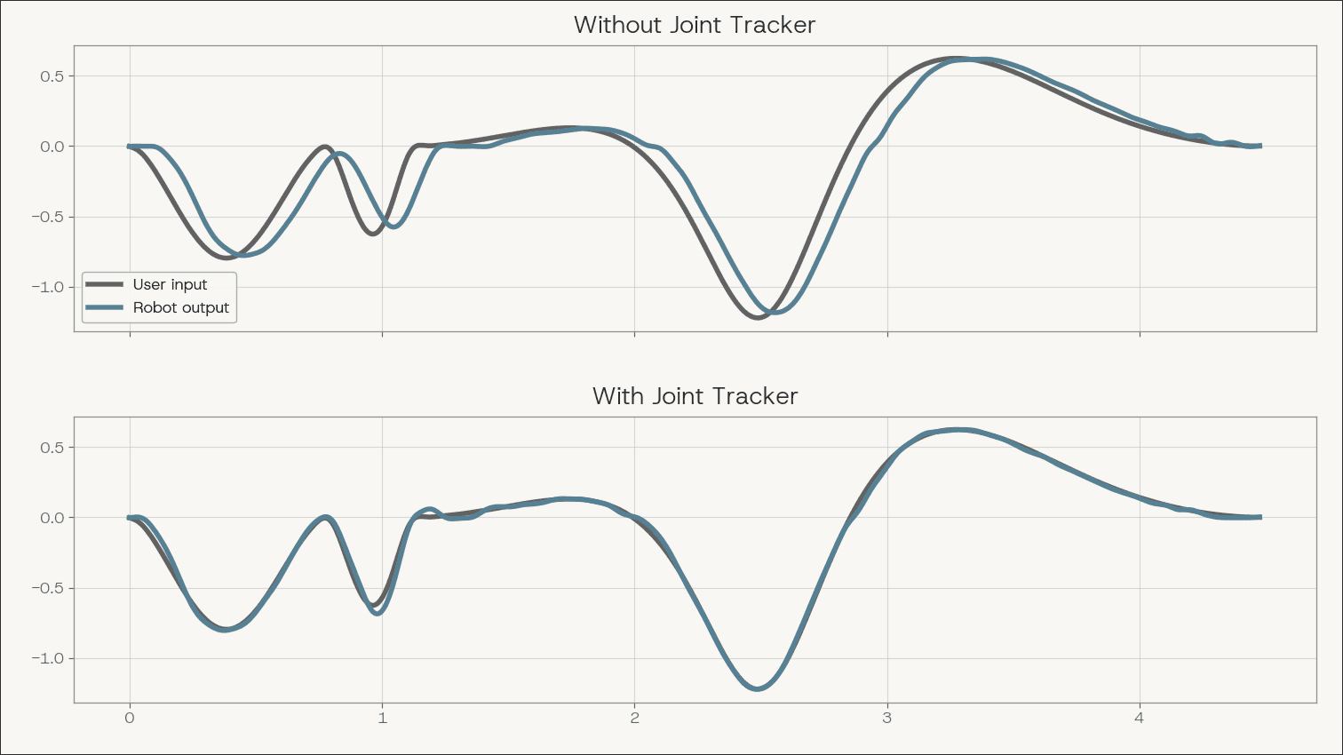
User input vs. robot output with and without Joint Tracker.
The speed behavior
The most informative result isn't the headline multiplier. It's what happens as you increase speed.
With Joint Tracker off, tracking error grows approximately linearly with trajectory speed. This is expected. The stock controller uses feedback only. At higher speeds, the joints lag further behind the reference because the controller is always reacting to error rather than anticipating it. Faster motion means more dynamic error, and the feedback loop cannot keep up.
With Joint Tracker on, tracking error stays approximately constant across the speed sweep.
This is the defining characteristic of feedforward compensation. The calibrated model predicts what each joint will do at a given command, and the controller pre-compensates. The compensation scales with the trajectory, so the tracking fidelity holds as speed increases.
For teleoperation, this has a direct consequence. An operator using a system with stock control learns to slow down — they move, wait for the robot to settle, check the position visually, correct, and continue. The system's tracking error creates a feedback loop that caps the operator's throughput.
When tracking error is constant across speed, that loop disappears. The operator can move at their natural pace and trust the end-effector to follow.
What drives the tracking error
Tracking error in teleoperation comes from two sources that compound in a way that is difficult for operators to compensate for.
Kinematic error is the static component. The robot's internal kinematic model — the DH parameters, the joint offsets, the frame alignments — doesn't exactly match the real machine. Manufacturing tolerances, installation differences, and wear all contribute. The result is a systematic TCP offset that varies with joint configuration. This is not a fixed bias. It changes across the workspace, so the operator cannot learn a single correction.
Dynamic error is the speed-dependent component. At speed, each joint lags behind, overshoots, or oscillates relative to the commanded trajectory. The end-effector follows a path that diverges from what was commanded, not just at the final position but throughout the entire motion.
Our products address both. Kinematic calibration (KineCal) corrects the geometric model using measured data from the specific robot. Model-based feedforward (Joint Tracker) uses per-joint dynamic models — calibrated to the actual physical response of each joint — to pre-compensate the trajectory before it reaches the actuator driver.
The key learning from our validation work is that controller performance is tied directly to model quality. When we tested early models that didn't accurately capture the joint dynamics, the controller compensated for behavior that didn't exist on the real robot. The tracking error metric appeared to improve, but the actual contour error — the spatial deviation from the intended path — got worse. The controller was generating oscillations to counteract dynamics that weren't there.
This reinforced something we now treat as a principle: model quality is the bottleneck, not algorithm quality. A good controller with a bad model will underperform a simple controller with an accurate model.
The calibration pipeline
Joint Tracker sits in the robot's motion command pipeline between trajectory generation and the actuator driver. The pipeline from the user's perspective has three steps.
Data collection. An automated calibration routine runs on the physical robot through the Reforge SDK. Controlled excitations exercise each joint through its dynamic range while sensors record the response.
Model identification. The calibration data is uploaded to a cloud API that runs system identification. The output is a set of per-joint dynamic models that capture how each joint actually responds to commands — its lag, its resonant behavior, its damping characteristics.
Deployment. The calibrated models deploy locally with the Joint Tracker controller. For teleoperation, Joint Tracker operates in a streaming mode — it processes trajectory commands in real time as they arrive from the operator interface.
The entire calibration process is designed to run without metrology equipment or specialized engineers. The data collection is automated. The model fitting runs in the cloud. The deployment is a software update.
What 5x means for the application
Reducing TCP tracking error from 8-10mm to roughly 2mm changes what a teleoperation system can physically do.
At 5mm or more of TCP error, the system is limited to tasks with coarse tolerances — moving boxes, gross positioning, pick-and-place where the gripper has generous clearance. The robot can't place things precisely enough for tasks like connector insertion, precision assembly, or any operation where the tolerance is smaller than the tracking error.
At 2mm, tasks that were previously out of reach become feasible. This isn't about making existing tasks marginally better. It's about expanding the set of tasks the system can attempt at all.
The per-unit variation question matters here too. Two robots of the same model, from the same manufacturer, will have different dynamic characteristics — different friction profiles, different structural stiffness, different backlash. A controller tuned on one unit doesn't produce the same tracking performance on another. Per-robot calibration handles this. For manufacturers with tight tolerances, models may hold across units of the same SKU. Where they don't, calibration can be integrated into the manufacturing workflow as a standard step.
What the data tells us
The validation results across two platforms demonstrate a few things clearly.
First, model-based feedforward control delivers a measurable and consistent improvement in tracking accuracy — 4x to 8x at the joint level, 4x to 6x at the TCP. The improvement is not marginal.
Second, the speed-invariant behavior is the more important result. Flat tracking error across speed means the system's accuracy doesn't degrade as operators move faster. For teleoperation, this directly translates to higher operator throughput without sacrificing fidelity.
Third, the converged accuracy of approximately 1.9mm TCP RMS on both platforms suggests a performance floor determined by effects outside the current model's scope. Understanding and reducing that floor is the next engineering problem.
The 5x number is real and validated. But the behavior underneath it — constant accuracy across speed, per-robot calibration, model quality as the bottleneck — is what actually matters for building teleoperation systems that work at production scale.
Reforge Robotics builds open-source motion control software that helps robots move faster and track more accurately. Book a demo for access to all our data or to learn more.
Iago Alves Pereira
Co-Founder and CTO
Share post
Written by
Iago Alves Pereira, Co-Founder and CTO